projects:sand_drawing:work_logs:improvements
Differences
This shows you the differences between two versions of the page.
| Both sides previous revisionPrevious revisionNext revision | Previous revision | ||
| projects:sand_drawing:work_logs:improvements [2020/04/17 05:11] – ↷ Page name changed from projects:sand_drawing:work_logs:5_improvements to projects:sand_drawing:work_logs:improvements tjhowse | projects:sand_drawing:work_logs:improvements [2020/05/12 09:21] (current) – tjhowse | ||
|---|---|---|---|
| Line 5: | Line 5: | ||
| ====== What I've done ====== | ====== What I've done ====== | ||
| - | I've made a few improvements | + | I've made a few improvements since [[projects: |
| - | * Added optoswitches for zeroing axes, | + | === Optoswitch mounts === |
| - | * Tabs on arm1 and arm2 to pass through the optos, | + | |
| - | * An arm to hold the optos. | + | |
| - | * Rotated the pin hole that holds arm1 onto shaft1, | + | |
| - | * Rotated the angle of the split that holds the two halves of arm1 together. | + | |
| + | In order to test the software before finishing the complete enclosure I needed a way to mount the optoswitches roughly where they'd be in the final product. I need the optoswitches to detect the position of the arms. Stepper motors have no positional feedback of their own, so the usual system is to move them until you detect them in a certain position. For my current 3d printer that is detected with some mechanical lever switches. For my old printer I used little paper flags and optoswitches. An optoswitch is an infra-red LED and a receiver facing eachother. If something comes between them a signal is generated. | ||
| + | |||
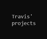
| + | {{: | ||
| + | |||
| + | I made this abstract-looking part to hold the optoswitches just past the ends of the arms. I could then attach little bits of plastic to the arms at the right height to pass through the optoswitch. With this information I could learn the position of the arms in absolute terms and then move to specific angles rather than just spinning around from whatever initial position the arms happened to be in at power-on. | ||
| + | |||
| + | === Rotated pin === | ||
| + | |||
| + | I made a small manufacturability improvement: | ||
| + | |||
| + | {{: | ||
| + | From this. | ||
| + | |||
| + | {{: | ||
| + | To this. | ||
| + | |||
| + | This way I can punch that pin through the piece in order to remove the arm. I did a similar thing for arm2. This lets me disassemble the thing non-destructively. | ||
| + | |||
| + | === Arm1 split === | ||
| + | |||
| + | {{: | ||
| + | Old. | ||
| + | |||
| + | {{: | ||
| + | New. | ||
| + | |||
| + | I had noticed that arm1 could bend slightly about the joint because the joint was in shear. It could twist slightly because it was the compression from the bolts causing friction between the touching faces. The tension in the belt could overwhelm this friction and the two faces would slide against each-other. | ||
| + | |||
| + | The new arrangement puts the bolts into tension and there is no force acting to shear the joint. | ||
| ====== What I want to accomplish next time ====== | ====== What I want to accomplish next time ====== | ||
| * Assemble everything | * Assemble everything | ||
projects/sand_drawing/work_logs/improvements.1587100315.txt.gz · Last modified: 2020/04/17 05:11 by tjhowse