Table of Contents
The Electronics
The Plan
I want this device to continue to operate for many many years. To achieve this I want to use as few components as possible, so there are few things to go wrong. PCB design is definitely my weakest area of expertise. I'd like to credit all the folk who helped with this project from Hackerspace Brisbane. Thanks y'all!
Supercapacitors
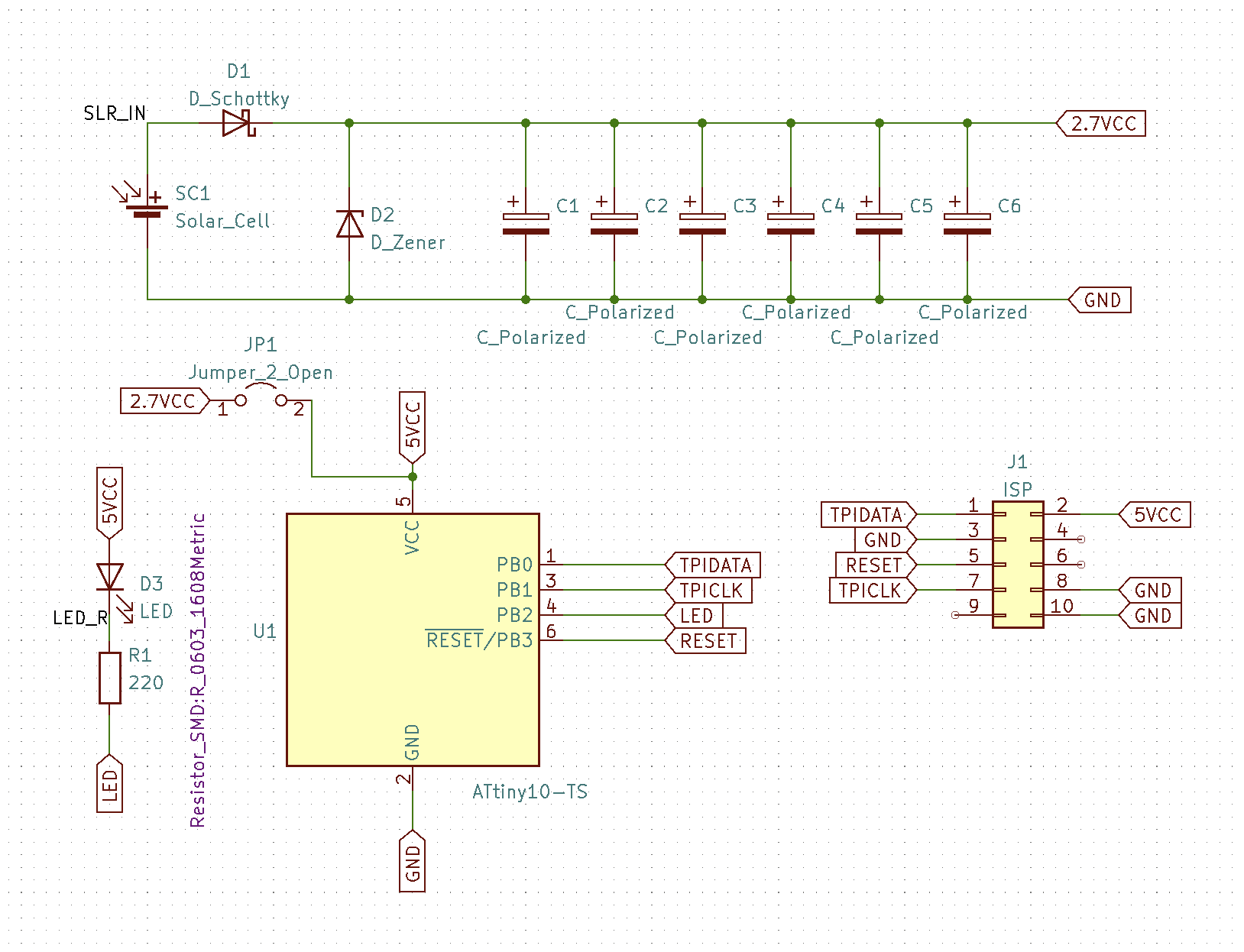
Supercapacitors outperform batteries in longevity, even if they have lower energy density. According to the research they tend to last longer with lower current. My design uses many capacitors in parallel to reduce the peak current, and limits the maximum charge voltage to substantially under their rated max. This voltage limitation will come from a zener diode in parallel with the capacitors.
Solar cell
I want to use a solar cell that produces a maximum voltage of approximately the rated voltage of the voltage protection zener. A more complex circuit would yield better efficiency, but I want absolute maximum reliability. A schottky diode is used to prevent current leaking backwards through the solar panel when it is not being illuminated.
Microprocessor
I chose the ATTiny10 due to its low power usage and wide voltage range. It uses the Atmel Tiny Programming Interface (TPI). It has 1kB of flash, 32B of RAM and no EEPROM. I wrote a proof-of-concept program to validate I could fit the necessary code into the strictly limited storage space available. I was able to fit a program that flashed a few sentences of text as morse code inside a few hundred bytes.
The Doing
The circuit
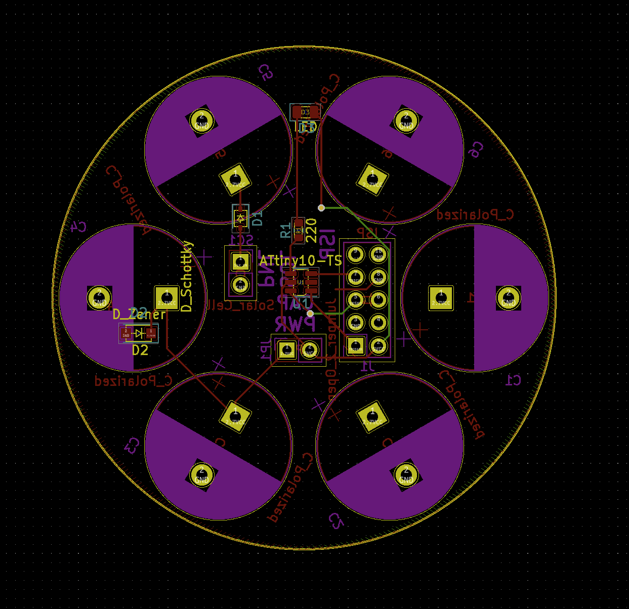
The PCB layout
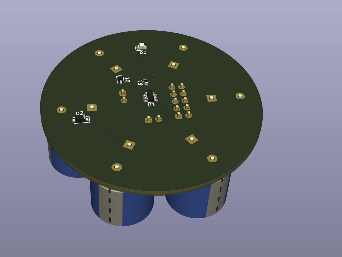
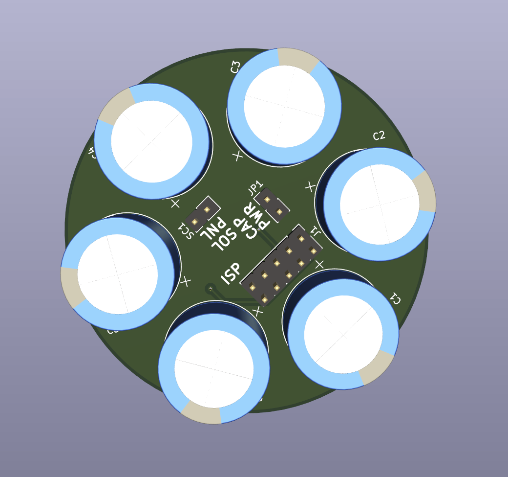
3D renders. The capacitors are actually 38mm high, far more than shown here, but I don't know how to resize the models used in this render.
The Waiting
Assembly
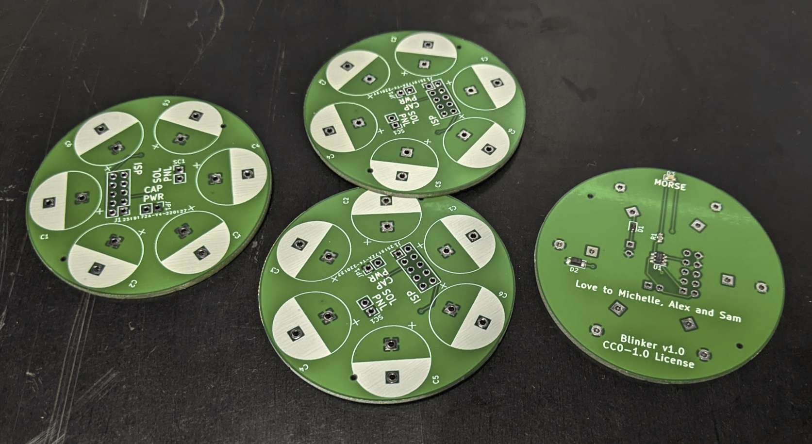
The PCBs arrived and I soldered on one 25F supercap, the ISP header and two 2×1 SIL headers. I set my benchtop PSU to 2.8v and connected it to the solar panel input. It started drawing several amps as the caps charged up. I quickly dialled down a 100mA current limit, and the voltage slowly increased to the limit of the zener.
Programming
I had quite a lot of trouble getting the firmware onto them:
- USB extension to my workbench was too long,
- 3.3v/5v selector needs to be on 5v,
- The firmware in the USPasp was too old to support TPI,
- The JP3 jumper was not installed, this is required to enable 1 MHz programming speeds,
- I had to use Zadig to install the libusbK v3.1.0.0 driver,
- Arduino IDE reporting avrdude failure when it was actually succeeding.
After solving all of those problems I eventually got some basic code onto it and and recorded a progress video.
Video
Next Time
There are a few major shortcomings to this design. It does not efficiently collect energy from the solar panel. I could get some extra energy by employing Maximum Power Point Tracking (MPPT). A single ZSPM4523AA1 would give me MPPT, reverse current protection (replacing the schottky diode) and voltage regulation (replacing the zener diode). Also, the useful voltage range of the capacitors is between 1.8v and 2.4v. The maximum is set by the zener diode, and the minimum is set by the microcontroller. If I used a boost converter, such as a LM27313, TPS6122x, LTC3108 or TPS61021, I could decrease the usable minimum capacitor voltage to 0.5v, giving us more available energy over a full discharge.

