What I want to accomplish
- Solve the previous problems I was having with rotor conductance
What I've done
My old design, as shown in the youtube videos, has big friction problems. The rotors would index together tightly in the correct alignment, but not reliably and the conductivity was poor. It was hard to get all 24 points touching simultaneously. I need a sprung connection.
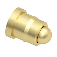
Enter: low profile beefy pogo pins.
If I mount these either in a 3d printed rotor, or solder them onto a PCB, I'll have some positive spring pressure making the contact.
The pogo pins can be surprisingly costly. The cheapest I've found was around AUD$0.25 each. Considering a full set of eight rotors with 26 connectors each needs 208 pins, which is AUD$52 in pogo pins alone. A cheaper spring contact option would be nice.
Using PCBs to form the rotor faces has a number of benefits. The rotor wiring can be baked into the PCB traces, so no tedious and error-prone manual wire soldering is required to link the 26 pins to the 26 pads. A rotor could consist of one or two PCBs with pins and pads on opposite sides, with the knurling and ratcheting built into the edge of the PCB.
However PCBs would probably drive up the cost significantly. Worth considering though.
Here are some links:
http://www.digikey.com/en/product-highlight/m/millmax/ultra-low-and-low-profile-spring-pins
http://www.digikey.com/en/product-highlight?f=474941729
https://www.nh-technology.de/en/federkontakt/plug-in-type-single
https://www.mill-max.com/products/stock/0967015207514110
https://www.mill-max.com/products/quick_search/low_profile_spring_loaded

