Table of Contents
What I want to accomplish
- Do the inverse kinematics,
- Check the bounds,
- Improve the kinematics.
What I've done
Inverse kinematics
This is a fancy term for “calculating the joint angles required to achieve a given tool position”. In our case the tool is the ball. I found a good guide to the maths at Applied Go. It's just some fancy trigonometry to calculate the angles for both arms. In order to integrate this logic with my specific robot I had to account for the fact that arm 2 rotates WRT arm 1 while arm 1 is moving.
An interesting and non-obvious (to me) fact I discovered during optimisation is that the two angles calculated for the joints are interchangeable if your arms are the same length. You can apply either angle to either joint and the tool position will be the same. I used this to my advantage when assigning the rotations to the stepper motors. The angles were assigned to the steppers based on which assignment would result in the least total stepper rotation.
Bounds checking
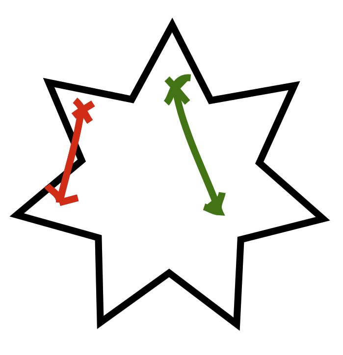
I wanted to make it impossible for the tool to hit the edge of the enclosure. I could depend on GCODE for this, but I would rather be able to account for silly coordinates and still prevent a crash. To solve this I implemented a system to filter every coordinate to ensure it is safely within the bounds of the octagon. I first check to see whether the point is inside - this is pretty straightforward for convex polygons. If the point is outside the octagon search for the two vertices that are closest to the point, then I find the point on the line between the two vertices that is closest to the target point. I then remap the target to this closest point.
This worked really well, and it should support many different types of convex enclosure shapes via the constants.ENCLOSURE_VERTICES list. However concave enclosure shapes are considerably more difficult, both in terms of bounds checking and also path planning.
In these cases I would probably rely on the GCODE to prevent crashes, since solving a pathfinding problem at runtime on a microcontroller would be hard.
Straight path motion
The inverse kinematics calculates an angle for each joint in the system. Initially I assigned the target angles to the stepper motors and each one rotated towards its target at the same rate. This would sometimes lead to weird paths if the rotation required to reach the targets was very different for each stepper. One stepper would reach its target rotation long before the other and there would be a bend in the path.
In order to smooth out the path I first tried scaling the speeds of the steppers based on the proportional distance it had to travel. This way a stepper with a required rotation of 30 degrees would travel at half the speed of the second stepper with a required rotation of 60 degrees. This means the two steppers would finish their moves at approximately the same time.
This approach still resulted in curved paths, since the rate of the movement needs to vary based on the kinematics of the system. This solution was accurate on average, but not actually accurate at any point but the start and end. The tool would actually move in an arc. This is bad in general terms, since it's reasonable to assume a robot moves directly between the coordinates specified in the GCODE, but it can also cause problems if that arc collides with the edge of the enclosure.
I needed to solve this. My initial thought was to break the path up into a number of intermediate points and move between them on the way to the end target point. I wasn't happy with this approach - I felt as though I should solve it “properly” and do the maths to work out the velocity profiles for the two steppers to result in a straight line. I gave up on solving this problem with my own brain and decided to look it up. It turns out this is a Hard Problem in non-cartesian robotics, and many solutions do exactly as I had imagined. With the reassurance that other engineers had been as lazy as me I proceeded with the dodgy numerical approach.
At the start of each move of a magnitude greater than PATH_SPLIT_SIZE I calculate a vector that moves towards the end target by at most PATH_SPLIT_SIZE units. This vector is used to offset the current position to a new intermediate target. This repeats until the tool is less than PATH_SPLIT_SIZE units from the target and the robot then does a move to the final target.
I initially tested with a PATH_SPLIT_SIZE of 5mm. This resulted in fairly noticeable judder in the movement, so I dropped it to 1mm and the movement is much smoother.
What I want to accomplish next time
- Build the electronics.
